120 GENERAL SAFETY NOTES Any person being involved in assembly disassembly start-up operation and maintenance of the mechanical seal must have read and understood this operating manual and in particular the safety notesWe recommend the user. DISP Double Stationary Seal with Flow Inducer Design Features and Customer Benefits DISP Pumping Performance True double mechanical seal with two sets of independent springs A safe double seal design.
Experimental Analysis Of Mechanical Seal Design With Enhanced Thermal Performance Semantic Scholar
With a lower k value the safety against thermal overload will increase but the mechanical seal may also lift off more easily.

. The following instructions describe the standard configurations. Seal faces can be lubricated by the process fluid or with double mechanical seals by a proper auxiliary fluid see chapter relevant to configurations. 522 Lubricate the shaft of the machine through the use of a liquid compatible with.
8 O Ring. Mechanical seals there is no more expensive shaft or sleeve replacements. EPDM Neoprene Nitrile Chemraz Kalrez and Viton are available.
Dual seal with bi-directional. To assure satisfactory operation handle seal with care. 12 represents an example of a production drawing.
Mixer Model Serial Number Item Number 4 O Ring. Therefore standard mechanical seals are used only for a pressure up to 10 bar. Mechanical seal drawing pdf Reply to ldk A number of them get some ability thats for sure.
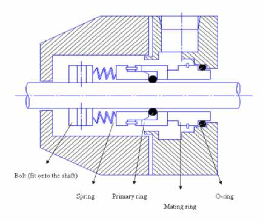
The seal between the stationary member 1 and stuffing box face ie. Identify the correct replacement seal. A mechanical seal has 4 main sealing points indicated by orange circles as per Figure 3.
These instructions can be used for all the series of Microtem mechanical seals unless otherwise decided. 9 Install the mechanical seal in the pump. To install a seal the pump would have to be taken off-line and disassembled.
External reservoir pressurized above seal chamber pressure providing barrier fluid to mechanical. Please Note that the number of springs. But Id personally just show my favorites in your nail Woman and they might replicate them But Id personally just show my favorites in your nail Woman and they might replicate them.
123 Assembly drawing A drawing that shows the various parts of a machine in their correct working locations is an assembly drawing as shown in fig. Mechanical seal and is defined as In practice k values are selected between 065 and 12. MORE FLEXIBILITY WITH SEALS MEANS LONGER SERVICE LIFE.
Probably the most widely recognized and also most common mechanical seal used in general service low pressure applications. Remove the seal drawing from packaging. Operating Manual MFL85Ndw-00 page 4 23 en MFL85Ndw-00 April 28 2016 Rev.
521 Make sure that the mechanical seal is corresponding to the assembly drawing. O-RINGS Aflas is standard. Sparingly lubricate the pump shaft with John Crane Silicone O-ring.
L1 Seal Head Operation Height OP. Verify that the direction of shaft rotation shown on the seal layout drawing matches the actual rotation of the pump shaft. ROTATING SEAL FACE Alpha sintered Silicon Carbide.
LESS FRICTION MEANS VALUABLE POWER SAVINGS. TM Mechanical Seals Selecting a replacement Mechanical Seal 861 Cranberry Court Oakville ON L6L 6J7 Phone. Seals have more flexibility than packing and are able to compensate for shaft deflection axial and radial end play as well as vibration and wear of the sealing faces.
D3 Counterbore or Seat OD. The inboard seal faces are not energized by the same springs that energize the outboard seal faces. Shall be constructed to 12 wg.
Spare part drawing 102220320 Lowara LOWARA FHE 50-16075 Version N917 0. Part Name and Part Drawing Number. 13There are several types of such drawings.
The seals are arranged by shaft size from smallest to largest. Drawing Codes D1 Shaft Size D2 Seal Head OD. HT L2 Seat Thickness DMR.
2m171 1 drawing note reference ie notes by symbol miscellaneous drawingdetail reference abbreviations general notes mechanical symbols and abbreviations note. Jurandir Primo PE 2012 PDH Online PDH Center 5272 Meadow Estates Drive Fairfax VA 22030-6658 Phone Fax. And sealed to smacna class c.
Make sure the seal matches the unit where installation will take place. A Place gland with stationary seal face and gasket on the pump shaft. With a lower k value the safety against thermal overload will increase but the mechanical seal may also lift off more easily.
For higher pressures balanced mechanical seals are used. This is known as the primary seal. Mechanical Seals - Fundamentals Instructor.
Mechanical seal selection The spring is in the product. Drawings of related components may be given on the same sheet. Refer to page 2 through 6 to identify the seal.
Buffer gas used to dilute seal leakage. In this case two mechanical seals are arranged in series. Type 5610 and 5610Q seals are designed for versatility and can be assembled in various ways.
Unlike an O-Ring seal the hydraulic diameter of a bellows seal is not a fixed geometric value. 5 ALPHA ALPHA Hydraulic force generated by. A connect to plan 75 B connect to plan 76 N 2 C A N 2 A Device to be located below pump shaft Used for hot applications or where products have low pressure and are harmfulhazardous.
07 1 ¹ 002232200 Mechanical seal CeramicCoalNBR 08 1 ¹ 002221281 O-Ring housing NBR 09A 1 130647143 Complete motor item number. SEAL TYPE The mechanical seal shown in the pump photograph is a Type 1 mechanical seal. The seal between the rotating member and shaft or shaft sleeve 4.
At Utex we refer to this type as RS-1 The assembly shown in the pump is configured with a. Jensen Type F Mechanical Seal Parts Drawing No. The product pressure acts additional to the spring on the rotating seal part.
Drawingdetail number sheet number re. Study the engineering layout drawing to confirm the proper seal arrangement for the pump being used. Lowara Deutschland GmbH - WB Subject.
Set screw the rotary unit to the shaft sleeve if seal is supplied with holding clips remove at this time. B Slide rotary unit on shaft sleeve and set the back of the rotary unit on the second scribe line as determined in step 8. Packing Although mechanical seals had been around for many decades by 1955 industry had converted only a small percentage of pumps from packing to mechanical seals.
Mechanical seal and is defined as In practice k values are selected between 065 and 12. If you are unable to identify the seal it will be necessary for you to measure the old seal for correct identification. Lower than seal pressure.
All symbols and abbreviations shown. Item 13 Wearing Parts. Drawing is an assembly drawing of a group of related parts that form a part in a more complicated machine.
Fig5 THE FUNDAMENTALS 3 Fig. Will vary depending upon seal bore. Seal all seams with ul 181 mastic.
In order for mechanical. TEMPERATURE-60F TO 400F -50C TO 204C PRESSURE 400 psi 27 bar SPEED 5000 fpm 25 ms 1 T he Liberator I cartridge seal patented incorporates advanced seal design features. Installing the Seal 1.
It is also influenced by. This is due to various reasons. Pdf-ETAPPE Version 20 - Build N917 Author.
An stable and complete layer of lubrication greatly affects the performance and the life of a mechanical seal. The seal between the rotating 3 and stationary faces 1. You can measure according to the Drawing Codes for the correct.

Pt Tjm Internasional Mechanical Seals

Sru Hyclean Double Mechanical Seals Complete Pdf

Pt Tjm Internasional Mechanical Seals
Ea560 En

R M7n M74n Unbalanced Mechanical Seal R M7n M74n

Sigma Seals Products

Pt Tjm Internasional Mechanical Seals

Pdf Performance Of Centrifugal Mechanical Face Seal
0 comments
Post a Comment